I2C温度計
参考サイト
使用モジュール
秋月通商 ADT7410使用 高精度・高分解能 I2C・16Bit 温度センサモジュール
J1J2を半田付けして基板上でSCL,SDAを10kΩのプルアップ
I2Cアドレス0x48(プログラム上は1ビットシフトして0x90)
ADT7410のレジスタ
Temperature Value Register (Register Address 0x00~0x01
| Adress | Bit | Default Value | Type | Name | Description |
|---|---|---|---|---|---|
| 0x00(MSB) | [14:8] | 0000000 | R | Temp | Temperature value in twos complement format |
| 15 | 0 | R | Sign | Sign bit, indicates if the temperature value is negative or positive | |
| 0x01(LSB) | 0 | 0 | R | TLOW flag/LSB0 | Flags a TLOW event if the configuration register, Register Address 0x03[7] = 0 (13-bit resolution). When the temperature value is below TLOW, this bit it set to 1. Contains the Least Significant Bit 0 of the 15-bit temperature value if the configuration register, Register Address 0x03[7] = 1 (16-bit resolution). |
| 1 | 0 | R | THIGH flag/LSB1 | Flags a THIGH event if the configuration register, Register Address 0x03[7] = 0 (13-bit resolution). When the temperature value is above THIGH, this bit it set to 1. Contains the Least Significant Bit 1 of the 15-bit temperature value if the configuration register, Register Address 0x03[7] = 1 (16-bit resolution). |
|
| 2 | 0 | R | TCRIT flag/LSB2 | Flags a TCRIT event if the configuration register, Register Address 0x03[7] = 0 (13-bit resolution). When the temperature value exceeds TCRIT, this bit it set to 1. Contains the Least Significant Bit 2 of the 15-bit temperature value if the configuration register, Register Address 0x03[7] = 1 (16-bit resolution). |
|
| [7:3] | 00000 | R | Temp | Temperature value in twos complement format. |
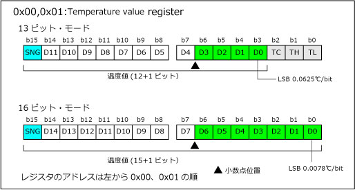
温度値の換算(13bit)
13ビットモードの場合は、レジスタ値の下位3ビットが不要ですので、レジスタ値を3ビット右にシフトした値で計算ます。
<正数の場合> 計算値=((MSB << 8) | (LSB&0 & f8)) >> 3
<負数の場合> 計算値=((MSB << 8) | (LSB&0 & f8) - 8192) >> 3
これを小数点位置下4桁のため まで16で割ります。
温度= 計算値 / 16
Status Register (Register Address 0x02)
| Bit | Default Value | Type | Name | Description |
|---|---|---|---|---|
| [3:0] | 0000 | R | Unused | Reads back 0. |
| 4 | 0 | R | TLOW | This bit is set to 1 when the temperature goes below the TLOW temperature limit. The bit clears to 0 when the status register is read and/or when the temperature measured goes back above the limit set in the setpoint TLOW + THYST registers. |
| 5 | 0 | R | THIGH | This bit is set to 1 when the temperature goes above the THIGH temperature limit. The bit clears to 0 when the status register is read and/or when the temperature measured goes back below the limit set in the setpoint THIGH − THYST registers. |
| 6 | 0 | R | TCRIT | This bit is set to 1 when the temperature goes above the TCRIT temperature limit. This bit clears to 0 when the status register is read and/or when the temperature measured goes back below the limit set in the setpoint TCRIT − THYST registers. |
| 7 | 1 | R | RDY | This bit goes low when the temperature conversion result is written into the temperature value register. It is reset to 1 when the temperature value register is read. In one-shot and 1 SPS modes, this bit is reset after a write to the one-shot bits. |
Configuration Register (Register Address 0x03)
| Bit | Default Value | Type | Name | Description |
|---|---|---|---|---|
| [1:0] | 00 | R/W | Fault queue | These two bits set the number of undertemperature/overtemperature faults that can occur before setting the INT and CT pins. This helps to avoid false triggering due to temperature noise. 00 = 1 fault (default). 01 = 2 faults. 10 = 3 faults. 11 = 4 faults. |
| 2 | 0 | R/W | CT pin polarity | This bit selects the output polarity of the CT pin. 0 = active low. 1 = active high. |
| 3 | 0 | R/W | INT pin polarity | This bit selects the output polarity of the INT pin. 0 = active low. 1 = active high. |
| 4 | 0 | R/W | INT/CT mode | This bit selects between comparator mode and interrupt mode. 0 = interrupt mode 1 = comparator mode |
| [6:5] | 00 | R/W | Operation mode | These two bits set the operational mode for the ADT7410. 00 = continuous conversion (default). When one conversion is finished, the ADT7410 starts another. 01 = one shot. Conversion time is typically 240 ms. 10 = 1 SPS mode. Conversion time is typically 60 ms. This operational mode reduces the average current consumption. 11 = shutdown. All circuitry except interface circuitry is powered down. |
| 7 | 0 | R/W | Resolution | This bit sets up the resolution of the ADC when converting. 0 = 13-bit resolution. Sign bit + 12 bits gives a temperature resolution of 0.0625°C. 1 = 16-bit resolution. Sign bit + 15 bits gives a temperature resolution of 0.0078°C. |
プログラム
レジスタ書込
I2C.wite(I2Cアドレス, (char[]){レジスタアドレス, レジスタ値}, 2);
レジスタ読込
I2C.wite(I2Cアドレス, (char[]){レジスタアドレス}, 1);
char data[length];
I2C.read(I2Cアドレス, data, length);
プログラム例
#include "mbed.h"

I2C myi2c(dp5, dp27);   // I2Cピン
DigitalOut myled(LED1); // LED
int addr = 0x90;        // I2Cアドレス(0x48)

// 設定
void SetConfig(char val){
    myi2c.write(addr,(char[]){0x03,val},2);
}

// 設定取得
char GetConfig(){
    myi2c.write(addr,(char[]){0x03},1,true);

    char read[1];
    myi2c.read(addr,read,1);
    return read[0];
}

// 温度取得
float GetTemp(){
    myi2c.write(addr,(char[]){0x00},1,true);

    char read[2];
    myi2c.read(addr,read,2);

    int value = (((read[0] & 0x7f) << 8 ) + (read[1] & 0xf8)) >> 3;
    if(read[0] & 0x80)
        value -= 8192;

    return value / 16.0f;
}

int main() {
    myi2c.frequency(400000);
    while(1) {
        myled = !myled;
        wait(0.2);
        printf("%f\n", GetTemp());
    }
}